Making My First (Real) PCB
Making a cool PCB has been on my bucket list for a long time. I’ve built a few smaller boards before, but none of them really looked interesting or had particularly fun functionality. The biggest problem was simple: I had no idea what to actually make. Then I asked around for ideas, and someone suggested an UNO card-themed PCB. The moment I heard it, I already had a clear design in mind.
DISCLAIMER: I have limited knowledge of electrical design and related topics, but I tried my best anyways :) Also, this blog post was written about a year after I lost interest in the project. This is a really bad habit as a lot of detail was lost in the meantime. So take this as advice and do your writeups in parallel to your projects!
Initial Planning
I started the project by writing down some hard requirements. The PCB should
- look cool (lol)
- have LEDs
- have programmable LED animations
Visual Design
KiCAD has a builtin image converter to convert black and white images to a Front Silkscreen layer. So all I had to do was to search for “uno reverse card black and white” on google and choose an image.
I decided to go with a 1:1 scale (5.7cm x 8.7cm), as the card is not so big that PCB manufacturing costs would be unreasonably high. With the dimensions I drew the outline for the PCB in FreeCAD, exported it as DXF and imported it into KiCAD. The outline of the board is not so complex that I had to design it in FreeCAD, but using the Draw Arcs function in KiCAD is just a pain to use.
Components
At first I chose the size for the LEDs. After comparing various sizes on the board render in KiCAD, I settled for 0805 LEDs. At this point I never soldered this size myself, but it certainly looked doable. The size of other components is not as important as they will be on the backside of the board.
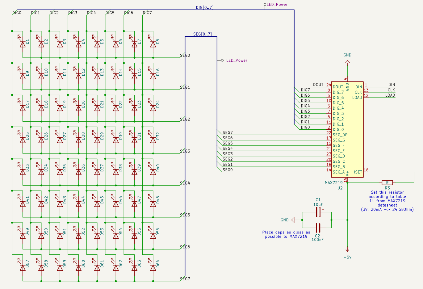
The next important decision was the LED driver. The first (and only) one that came to my mind was the MAX7219. It is a common driver for 7 segment displays or LED matrices which can be controlled via SPI and can drive up to individual 64 LEDs1. Fully wired up it looks like the following:
For development I chose to use a ATmega328P (desoldered from a Arduino Nano) as it is probably the easiest microcontroller to program with the Arduino framework.
Last but not least I added three buttons to the design to be able to set brightness of the LEDs and select an animation.
Layout
Laying out the 64 LEDs on the board was harder than expected, so I partly automated the process. To get a perfect oval I made use of the KiCAD python API. Below is a render of the final result.
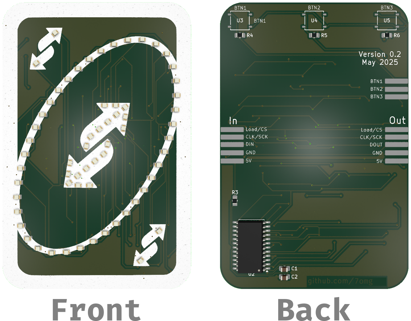
Note that the ATmega328P was not placed on the board in this revision of the board as I intended to use an STM32 for the final version. Instead, I exposed the SPI interface of the MAX7219 on the left side of the board (back view) and also added a output interface for potential daisy-chaining of the boards.
Firmware
Writing the firmware was pretty straight forward. Only mapping which bit corresponds to which LED on the board was kind of annoying to figure out in hindsight.
I added support for two animation types: hardcoded frame-by-frame animations and animations described by functions. The benefit of the latter is that complex animations can be described without having a huge impact on the program size.
Also, I started implementing a web-based tool to simplify creating animation frames, but I never finished it as web-development sucks.
Assembly
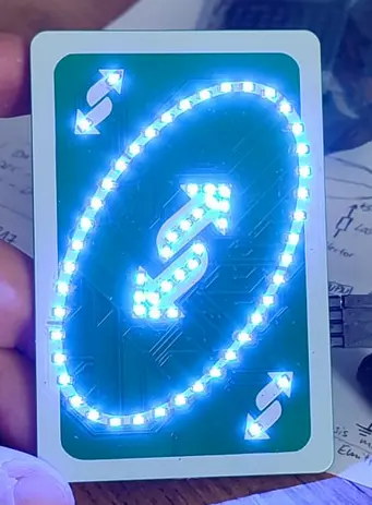
Unfortunately I didn’t shot an assembly timelapse for this project just yet :( But here is an image of the board fully assembled and with all LEDs turned on:
And here is a GIF of a animation I programmed (sorry for bad quality):
All files to this project can be found on my github repo.